

Key Takeaways
A suspected ECU fault should be treated as a diagnosis to prove, not a part to guess at. Work from the vehicle’s symptoms through power, ground, wiring, codes, and related systems before deciding on a repair.
- An ECU manages engine functions by processing sensor information and controlling outputs.
- Starting, stalling, misfires, warning lights, and poor economy can have many causes.
- Scan codes are useful evidence, but they rarely identify a failed ECU by themselves.
- Battery voltage, grounds, connectors, and wiring should be checked before condemning the module.
- A replacement ECU may require programming, coding, or security matching before the vehicle will run.
Understand what the ECU does and why it fails
The engine control unit, often called the ECM, is a computer that receives information from sensors and commands devices such as injectors, ignition components, and throttle controls. When people search for How to diagnose a faulty engine control unit (ECU), they are often starting with a symptom rather than proof of an internal computer failure. A careful diagnosis separates those two things. The process is part electrical testing, part mechanical inspection, and part comparison with manufacturer data.
How the ECU controls engine performance
The ECU continually interprets signals such as engine speed, temperature, throttle position, airflow, and oxygen content. It then adjusts fuel delivery, ignition timing, idle control, and emissions-related operation within the limits set by the vehicle software. That makes the ECU central to engine management, but it does not make every engine problem an ECU problem. A useful overview of technology in practice also helps explain why a computer system must be assessed through its inputs, processing, and outputs rather than through one symptom alone.
Common causes of ECU failure
Heat, vibration, water intrusion, electrical surges, reverse-polarity jump starts, damaged connectors, and poor charging-system performance can all threaten electronic modules. Software or memory faults may also interfere with communication or normal control. Look for the event that came before the fault: a flooded compartment, wiring repair, flat battery, jump start, or unsuccessful programming attempt often provides an important clue.
Symptoms that may indicate an ECU problem
Possible signs include intermittent cranking or starting, stalling, unstable idle, reduced power, repeated misfires, unusual fuel consumption, or a warning light that returns after clearing. Loss of communication with a scan tool is another concern, especially when power and ground are confirmed. These signs increase suspicion, but they still need to be tested against the vehicle’s wiring diagram and service information.
Why other faults can mimic ECU failure
A failed crankshaft sensor can prevent starting, a weak relay can interrupt module power, and a corroded ground can create several unrelated-looking codes. A leaking injector, damaged ignition coil, vacuum leak, or low fuel pressure can also make the engine feel electronically controlled when the underlying fault is elsewhere. The principle is simple: prove the circuit and the component before replacing an expensive module.
Check the vehicle’s symptoms and warning signs
Begin with a written account of what the driver experienced, including when the fault occurs and whether the engine was hot, cold, wet, accelerating, or idling. Note whether the vehicle cranks normally, starts and dies, or does not crank at all. This first record prevents a brief intermittent symptom from being lost during later testing.

Intermittent starting and stalling issues
Ask whether the starter turns the engine at a normal speed and whether the failure changes after the vehicle sits. An ECU cannot calculate engine operation correctly if it loses a crank or camshaft signal, and it cannot operate reliably if its supply voltage drops during cranking. Reproducing the symptom while monitoring voltage and scan-tool communication is more useful than repeatedly trying to start the car.
Misfires, poor acceleration, and rough idling
A rough idle or loss of power may result from ignition, fuel, air, compression, or sensor problems. Check whether the misfire follows a particular cylinder, appears under load, or occurs only after warm-up. If the ECU is commanding a normal response but a coil, injector, or air system is failing, replacing the ECU will not correct the symptom.
Unusual fuel consumption or emissions
A damaged oxygen sensor, coolant-temperature sensor, fuel injector, or intake leak can change fueling and emissions without any internal ECU defect. Record fuel-trim data, exhaust symptoms, and the conditions under which economy changed. Persistent rich or lean operation should lead to a system-wide inspection rather than an immediate module replacement.
Warning lights and abnormal dashboard behavior
A check-engine light is a request to investigate stored information, not a verdict. Observe whether other warning lamps appear together, whether gauges reset, and whether the diagnostic connector communicates consistently. For a workshop documenting its findings, Digital Vehicle Inspection software can fit the inspection workflow when photos or video are used to explain visible vehicle conditions to a customer.
Scan for diagnostic trouble codes
Connect a suitable scan tool only after confirming the battery is adequately charged and the ignition is in the required position. Save the codes before clearing anything, because erasing them can remove useful context. A scan is a starting point that helps direct testing; it is not a substitute for circuit diagnosis.
Choosing a compatible OBD-II scanner
Use a scanner that supports the vehicle’s model year, engine, and relevant control modules. Basic readers may display generic emissions codes, while more capable equipment can access manufacturer-specific data, pending faults, freeze-frame records, and live parameters. Follow the tool and vehicle instructions, particularly where low battery voltage could interrupt communication.
Recording and interpreting ECU fault codes
Write down each code exactly, along with whether it is current, pending, or stored. Read the definition as a description of the monitored circuit, not as a declaration that the ECU has failed. A sensor-circuit code may point to the sensor, its reference voltage, its ground, its signal wire, or the module’s ability to read that signal.
Using freeze-frame and live-data information
Freeze-frame data shows the conditions present when a fault was recorded, such as engine speed, temperature, load, and voltage. Live data lets you watch those values while the engine starts, idles, or is driven. Compare the readings with service specifications and with what the engine is physically doing; an implausible value is a clue that needs a circuit-level check.
The scan tool becomes much more useful when its readings are tied to a repeatable symptom. Capture the moment a signal disappears or voltage falls, rather than collecting pages of values without a testing question.
When a code does not prove the ECU is faulty
A code identifies the system that noticed an abnormal condition. It does not automatically identify the failed part. Before condemning the ECU, confirm the relevant fuse, relay, power feed, ground, wiring, connector fit, sensor operation, and communication circuit. A practical ECU diagnostic guide makes the same central distinction: test the surrounding systems before accepting a costly replacement.
Inspect the ECU’s power, ground, and connections
Many apparent computer failures are supply problems. Voltage can be present with the key on yet collapse during cranking, or a ground can look intact until current flows through it. Inspect and test these basics before probing delicate control circuits.
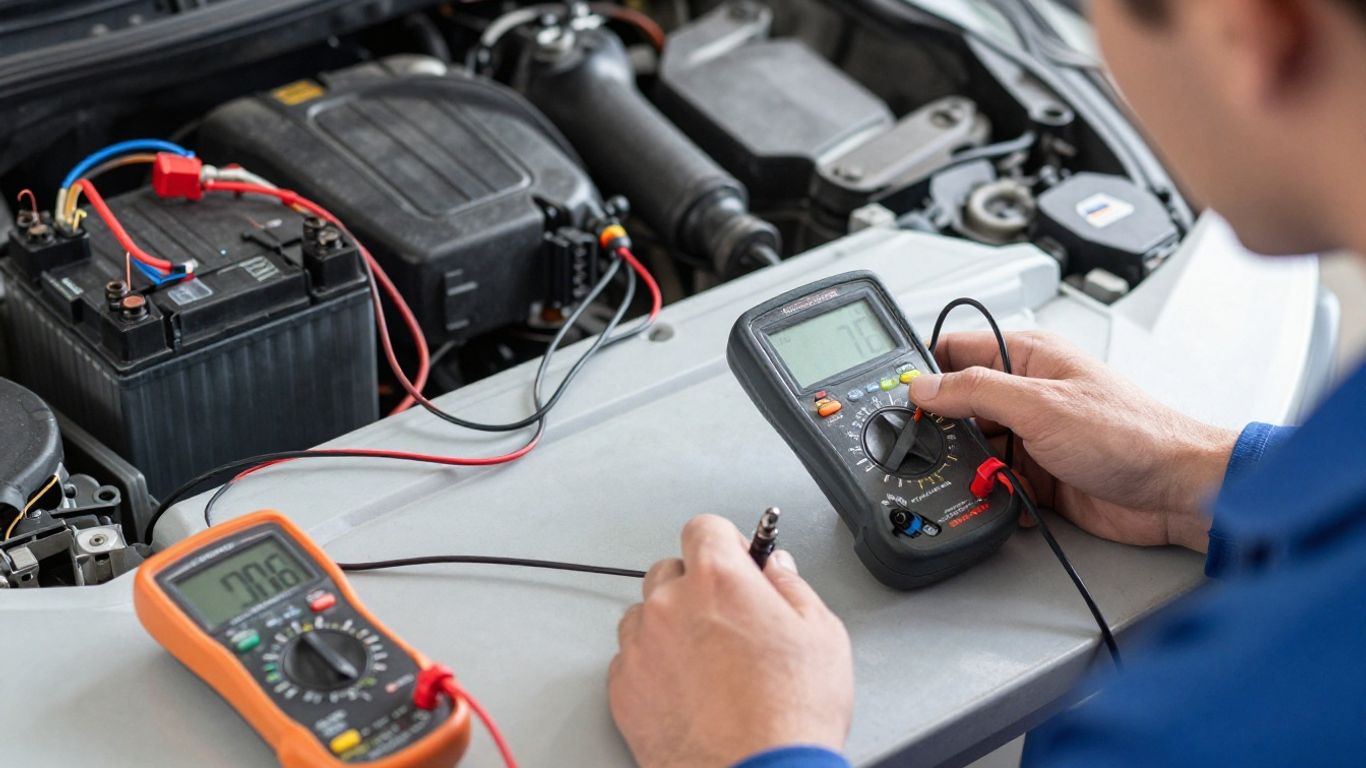
Checking battery voltage and charging-system output
Measure battery voltage at rest, during cranking, and with the engine running. The exact acceptable values depend on the vehicle and test conditions, so use the manufacturer’s specifications rather than a universal guess. Check charging output and battery terminals as well, because unstable system voltage can create multiple module and communication faults.
Testing ECU power supply circuits
Use the wiring diagram to identify every required feed, including ignition-switched and constant battery supplies. Test at the ECU connector with the circuit connected when possible, since an unloaded voltage reading can hide a weak connection. If power is missing, move upstream through the fuse, relay, splice, and wiring instead of replacing the ECU.
Verifying ground connections and voltage drop
A ground connection can appear clean and still have excessive resistance. Perform a voltage-drop test while the circuit is operating, placing the meter leads across the suspected ground path. The lower the measured drop, the more confidence you have that current is returning through the intended path; compare the result with the service limit.
Looking for corrosion, moisture, and damaged wiring
Disconnect the battery according to the service procedure before unplugging the ECU. Inspect terminals for pushed-back pins, oxidation, looseness, water tracks, and signs of overheating. Follow the harness toward the engine and body for chafing or stretched sections, then repair the underlying moisture or wiring cause before fitting another module.
Test ECU inputs and outputs with a multimeter
A multimeter can confirm whether a circuit has power, ground, continuity, or a plausible signal. It cannot by itself prove that the ECU’s internal software or processing is correct. Work slowly, identify the terminal from the diagram, and record readings with the operating condition beside them.
Following the vehicle’s wiring diagram
Do not rely on connector position alone, because similar plugs and wire colors can mislead. The diagram shows the circuit path, shared grounds, reference supplies, sensor returns, and controlled outputs. A clear test plan is much easier to produce when the question is specific, much like using an R.C.T.F. framework to define a role, context, task, and format before requesting an answer.
Measuring sensor reference voltage
Many sensors receive a regulated reference supply from the ECU. With the connector and ignition in the specified state, measure the reference against the correct sensor ground, then check whether it remains stable while the fault occurs. A missing reference may reflect a shorted sensor or wiring fault, not a failed module, so isolate the circuit before drawing a conclusion.
Checking signal circuits and continuity
Check continuity only on a de-energized circuit and inspect for unwanted continuity to ground or battery voltage. For changing signals, a meter may show an average rather than the actual waveform, so an oscilloscope or scan-tool comparison may be more appropriate. A useful multimeter testing method can guide the basic checks, but vehicle-specific pinouts and limits remain decisive.
Avoiding damage to sensitive ECU terminals
Never force a meter probe into a terminal or bridge adjacent pins. Use suitable back-probes, fused test leads, and the manufacturer’s connector procedure. Disconnect power before resistance testing, and avoid applying an external voltage to a circuit unless the service information explicitly permits it.
Rule out related engine and control-system problems
The ECU works as part of a larger chain. Sensors provide information, wiring carries it, actuators respond, and mechanical systems create the conditions the ECU is trying to manage. Testing that chain keeps a familiar symptom from becoming an incorrect computer diagnosis.
Testing sensors that can trigger ECU-like symptoms
Prioritize the sensors tied to the reported condition: crank and cam sensors for starting, airflow or pressure sensors for load calculation, temperature sensors for fueling, and oxygen sensors for mixture correction. Compare their signals with known engine conditions and manufacturer limits. If a sensor fails only when hot or vibrating, a static resistance test may miss the fault.
Checking fuses, relays, and communication networks
Inspect fuses on both sides with the circuit active, and test relays under load when possible. If a scan tool cannot communicate, check connector power, ground, network wiring, and other modules on the same communication bus. One shorted module or damaged network wire can make a healthy ECU appear absent.
Inspecting fuel, ignition, and air-delivery systems
Verify fuel pressure, injector operation, spark quality, intake leaks, throttle movement, and engine compression as appropriate to the symptom. A misfire diagnosis should include the coil, plug, injector, and mechanical condition before the ECU is blamed. The aim is not to test every vehicle system blindly, but to eliminate realistic alternatives in a sensible order.
Comparing live data with manufacturer specifications
Use service information for expected ranges, plausibility relationships, and test temperatures. For example, engine speed should appear during cranking, temperature should change gradually, and throttle data should agree with pedal or plate position where the vehicle uses those signals. A general ECU failure symptoms guide can help organize observations, but the vehicle’s own specifications take priority.
Confirm the diagnosis and choose a repair
An ECU should be considered faulty only after the evidence points inward: correct power and ground, intact wiring, valid inputs, suitable operating conditions, and outputs that do not respond as commanded. Record the tests and results so another technician can follow the reasoning. That documentation also protects against replacing a module when a simpler repair would have solved the problem.
When professional ECU testing is necessary
Seek specialist help when the module has internal damage, loses communication despite verified circuits, shows memory or processing faults, or requires bench testing. Professional testing may also be appropriate when the vehicle uses complex immobilizer, network, or programming procedures. Stop if the diagnosis requires opening the module or applying signals you cannot safely control.
Evaluating reprogramming, repair, or replacement
Reprogramming may address a documented software issue, while repair may be suitable for certain internal electrical failures. Replacement is a different decision and should follow confirmation that the original unit is defective. Ask what caused the failure, whether the replacement is tested, and what programming or coding will be required afterward.
Matching a replacement ECU to the vehicle
The replacement must match the vehicle’s hardware, software, engine configuration, and security requirements. Some vehicles require immobilizer pairing, coding, adaptation, or a software download before starting. Confirm compatibility by part number and vehicle data, and follow the manufacturer’s procedure rather than assuming a visually similar unit will work.
Clearing codes and verifying the repair through a road test
Clear codes only after recording them and completing the repair. Recheck communication, starting, idle quality, live data, warning lights, and the original symptom before driving. Then perform a controlled road test across the conditions that caused the fault, rescan for pending or returning codes, and keep the final results with the repair record.
Conclusion
A sound ECU diagnosis follows evidence from the driver’s complaint to the scan data, electrical supply, wiring, sensor inputs, controlled outputs, and related mechanical systems. Taking that sequence seriously can prevent an unnecessary module replacement and make the eventual repair easier to verify.
Frequently Asked Questions
What is the first sign of a failing ECU?
There is no single first sign. Intermittent starting, stalling, rough running, warning lights, communication loss, and unusual fueling can all occur, but each also has non-ECU causes.
Can a bad battery make an ECU look faulty?
Yes. Low cranking voltage, poor battery connections, and charging faults can interrupt module operation or communication and create misleading trouble codes.
Does a check-engine light mean the ECU is bad?
No. The light means the vehicle detected a monitored fault. The cause may be a sensor, actuator, wiring fault, fuel problem, ignition issue, or the ECU itself.
Can an ECU be tested with a multimeter?
A multimeter can test many external power, ground, reference, continuity, and signal circuits. It usually cannot fully assess internal processing, memory, or software integrity.
Should ECU connectors be unplugged while the battery is connected?
Usually no. Follow the vehicle’s service procedure, switch off the ignition, and disconnect the battery when required to prevent shorts or damage to terminals and modules.
Does a replacement ECU need programming?
Often it may need coding, software configuration, adaptation, or immobilizer pairing. The exact requirement depends on the vehicle and replacement unit.
How can a repair be confirmed?
Restore the original operating conditions, verify the electrical tests, clear recorded codes, reproduce the symptom safely, complete a road test, and rescan for returning faults.